
How to make a Lab Bench Power Supply || Build your own DIY Variable Power Supply
When we work on different electronics projects, we need different voltages and current. That problem can be solved by a lab bench power supply. It gives you adjustable voltage and current. But buying a commercial one can cost a lot.
Don’t worry— Here’s an in-depth step-by-step guide on how to build your own Variable Power Supply.
Features of this Lab Bench Power Supply
⇨Switch Between DC and AC Input Sources
⇨Precisely Controlled output voltage and current
⇨Displays output Volt & Amp with Power Status Indicator
⇨Stable and Adjustable DC Power Source for any Project
Required Components for build Lab Bench Power Supply
| Part’s Name | Quantity | Function |
|---|---|---|
| XL4016E1-DC-DC Buck Converter | 1X | Adjust DC Voltage & Current |
| LM2596 Adjustable Voltage Regulator | 1X | Provides 12V power for fan and voltmeter |
| 10KΩ Multi-turn Potentiometers-3590S-2-103 | 2X | Precise adjustment of Voltage and Current |
| Digital Volt-Amp Meter | 1X | Real-time Display Volt & Amp output |
| DPDT Toggle Switch | 1X | Switch between two input sources |
| SMPS Power Supply | 1X | DC Power input source |
| Banana Plug | 2X | Output connections |
| 12V DC Brushless Exhaust Fan | 1X | Cooling the buck converter |
| 5mm LEDs | 2X | Power status indicators |
| Resistors-(1 KΩ,2.2 KΩ) | 2X | Current limiting for LEDs |
| AC Power Jack | 1X | AC Power input |
| AC Fuse | 1X | Overcurrent Protection |
| SPDT Rocker Switch | 1X | Power ON SMPS |
| DC Power Jack | 1X | DC Power input |
| 2 Pin Terminal Block | 1X | DC Power input |

Step-by-Step Build process of Lab Bench Power Supply

Step 1: Prepare the Enclosure


Step 2: AC Power Input

Mount SPDT Rocker Switch , AC input jacks, AC Fuse on panel and Connect all Connections as per Circuit Diagram.

Step 3: DC Power Input

Mount 2 Pin Terminal Block,DC Power Jack on panel and Connect all Connections as per Circuit Diagram.

Step 4: Wiring the SMPS Power Supply

Warning:
Step 5: Wiring the Dual DC Input with Toggle Switch
DPDT Toggle Switch accepts DC two input sources at a time and help to select one input at a time.


Step 6: Replace on board Trimpots with external Multi-Turn Potentiometer

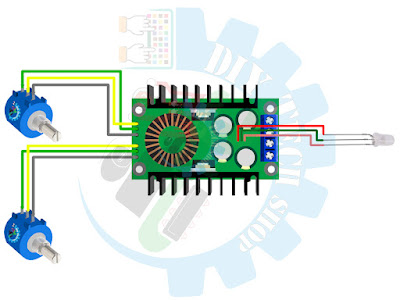
Extend the connections of on board Indicators LED and mount on panel

Step 7: Setup LM2596 for Accessory Power


Step 8: Connect DC Power supply to LM2596 & XL4016E1 Module


Step 9:Power Supply to Volt-Amp Meter


Step 10:XL4016E1-Buck Converter Module Setup

Connect the Voltage sense (Yellow thin) wires to Positive Output of the Buck Converter.


Connect the Red (thick) wire of Volt-Amp Meter to the Negative Output Banana Plug.
Step 11:Cooling Fan Installation
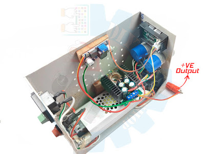
Step 12:Final Assembly
⇨Ensure all wiring connections are tight and Check for any exposed wires.


Detailed Circuit Diagram of Lab Bench Power Supply
Here, a Detailed circuit diagram showing the exact wiring between all components.

Step By Step Video Tutorial Of Building a Lab Bench Power Supply
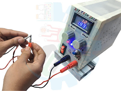
Final Testing of the Bench Lab Power Supply
⇨Check polarity of wire before connecting input power.
Warning:Without proper knowledge, Working with AC Voltage is Extremely Dangerous. I am not responsible for any Injuries or Damages caused by this power supply during build or use.
⇨Set the DPDT switch for select Between Power Inputs.DPDT Switch allows one input at a time.
⇨Adjust voltage precisely using the multi-turn potentiometers.

⇨Short the Output Terminal to Measure the Current.
Conclusion
Congratulations! You are successfully built your own powerful and cost-effective Lab Bench Power Supply. Now this variable power supply is ready to power up your projects.
Thank you for being a part of “How to make a Lab Bench Power Supply "project.
Happy Building!
Warm regards,
Diy Tech Shop.


